


April 29, 2024
When selecting the right Coated Inserts cutting insert for a specific cutting tool holder, there are several key considerations to take into account. Firstly, the cutting insert's compatibility with the cutting tool holder must be ensured. This means ensuring that the insert has the correct dimensions and mounting style for the holder. Secondly, the cutting insert must be suited to the material being machined. The type of cutting insert should match the material being cut, taking into account factors such as the hardness, toughness and type of material. Thirdly, the cutting insert must be able to withstand the forces and temperatures generated during the machining process. The cutting insert must be made from a material that can withstand the stress of machining and maintain its cutting edge. Finally, the design of the cutting insert must be appropriate for the machining SNMG Insert process. For example, the number of cutting edges must be suitable for the type of machining being performed and the shape of the insert must be suitable for the cutting tool holder.
The Cemented Carbide Blog: CNC Inserts China
Posted by: philipryan at
03:08 AM
| Comments (1)
| Add Comment
Post contains 197 words, total size 2 kb.
April 26, 2024
Diamond-coated cutting inserts are an innovative tool used to tackle hard materials. This is a cutting-edge technology that is helping to improve the efficiency and productivity of machining operations. Diamond-coated cutting inserts have a number of advantages, including the ability to cut harder materials with less wear and tear on the cutting tools, longer tool life, and improved cutting feed rates. In this article, we will explore the benefits of using diamond-coated cutting inserts in hard material machining.
The first benefit of using diamond-coated cutting inserts is that they can cut harder materials with less wear and tear on the cutting tools. The diamond layer on the inserts helps to provide increased hardness and therefore improved cutting performance. This also helps to reduce the amount of time required to complete the machining process. Additionally, the diamond layer helps to create a smoother cutting surface Cutting Inserts and allows for greater accuracy and precision when cutting hard materials.
Another benefit of using diamond-coated cutting inserts is the longer tool life. The diamond layer on the inserts helps to improve the life of the cutting tools, as it can withstand the abrasive forces generated during machining. This helps to reduce tooling costs and increase overall productivity. Additionally, the diamond layer helps to reduce heat generation during machining, which is important for maintaining the integrity of the material being cut.
Finally, diamond-coated cutting inserts help to improve cutting feed rates. The diamond layer helps to reduce friction and improve the efficiency of the cutting process, which in turn helps to reduce cutting time. This can drastically improve production times as well as improving the quality of the end product.
In conclusion, the benefits of Carbide Inserts using diamond-coated cutting inserts in hard material machining are numerous. They allow for more efficient and precise cutting with less wear and tear on the cutting tools, longer tool life, and improved cutting feed rates. These advantages help to improve the productivity of machining operations and ultimately reduce costs. If you are in the market for a cutting tool that is reliable and effective, consider investing in diamond-coated cutting inserts.
The Cemented Carbide Blog: Cemented Carbide Inserts
Posted by: philipryan at
07:06 AM
| No Comments
| Add Comment
Post contains 372 words, total size 3 kb.
April 20, 2024
Greenleaf’s Excelerator end and face mills are designed for high-performance milling in difficult-to-machine materials using either carbide or ceramic TCGT Insert inserts in the same cutter bodies. The milling cutters are available in both coarse and fine pitch designs.
According to the company, the fine-pitch mills are said to allow for higher productivity, increased speed and feeds, higher material removal rates, and better process stability with through air/coolant. The increased number of teeth over the rod peeling inserts coarse-pitch mills, combined with insert grades, is said to maximize efficiency.
The fine-pitch mills perform well in roughing applications that require more tooling stability. Having more teeth in the cut reduces the chance of vibration when machining forgings with heavy interruptions. Better engagement provided by the increased number of teeth also produces better surface finish than coarse-pitch milling cutters.
Greenleaf’s fine-pitch Excelerator end mills are available in diameters ranging from 3/8" to 2 ½" (10 to 63 mm). The fine-pitch face mills are available in diameters ranging from 3" to 12" (80 to 315 mm).
The Cemented Carbide Blog: Drilling Inserts
Posted by: philipryan at
04:07 AM
| No Comments
| Add Comment
Post contains 188 words, total size 2 kb.
April 16, 2024
Water cutting, also known as water jet knife, referred to a kind of high-pressure water jet cutting technology, it’s high-pressure water cutting machine. Under the control of the computer, the workpiece can be carved arbitrarily, and it is less affected by the processed material quality. Due to its easy operation and good yield, water cutting is gradually becoming the mainstream cutting method in industrial cutting technology.
Historical Development
Early water cutting because the pressure of water is very small, and no abrasive is added, it can only be used to cut paper and other soft, low strength materials,which means its application range is very narrow.
Later, with the development of technology, high-pressure water pump can be used to cut more materials. Early water cutting relied entirely on the pressure of water to cut materials, but only cutting materials with lower strength than water pressure, the application is still limited.
Dr. Norman Franz has always been recognized as the father of the water knife. He was the first person to study ultra-high pressure (UHP) water knife cutting tools. Ultra-high pressure is defined as over 30 000 psi. Dr. Franz, a forestry engineer, wanted to find a new way to cut big trunks into the wood. In 1950, Franz first placed heavy objects on the water column, forcing water through a tiny nozzle. He acquired a short deep hole drilling inserts high-pressure jet (several times exceeding the current pressure) and was able to cut wood and other materials. His later research involved more continuous flow, but he found it very difficult to obtain continuous high pressures. At the same time, the life of parts is calculated in minutes, not weeks or months today.
In 1979, Dr. Mohamed Hashish began to study ways to increase the cutting energy of water knives in Frow’s research laboratory to cut metals and other hard materials. Dr. Hashish is recognized as the father of sand water knife. He invented the method of adding sand to an ordinary water knife. He uses garnet (a material commonly used on sandpaper) like sand. With this method, water knives (containing sand) can cut almost any material. In 1980, and water cutters were first used to cut metals, glass, and gravity turning inserts concrete.
Working principle of water jet cutting
The water-cut water jet starts from a pressurized pump and passes through a high-pressure tube to produce a pressure of 60,000 PSI, which is then ejected from the cutting nozzle. During the design process, small leaks can permanently damage the components and cause damage. Therefore, manufacturers and engineers will carefully handle the processing of high-pressure materials, using special technology to combine such machines. Users only need to know basic operational knowledge.
The cutting machine was applied in the industry in 1982, and it was first introduced in 1970. It is mainly used in the automotive, aerospace and glass industries in the industry, and the precision is continuously improved from these cuttings. The abrasive cutter can reach a pressure of 55,000 PSI, which is injected through a small nozzle at a speed of 762 m/s, which is 2.5 times the speed of sound.
Mixing the pomegranate sand into this high-speed water jet, mixing it in a mixing tube and then directly ejecting it from the sand tube to the material being processed at a speed of 305 m/s. This cutting process is actually a grinding and cutting process. The process, this power and movement are all produced by water.
The booster pump pressurizes the water again to achieve the desired pressure. It is worth noting that the abrasive cannot be added to the water or high-pressure water line because the line will wear through quickly. Therefore, it can only be added to the nozzle position to mix water and abrasive. At the same time, it can’t be too close to the exit, because it is necessary to give him a speed to accelerate, only the abrasive has a certain flow rate to have the cutting ability. In order to avoid the abrasive mixing of the abrasive and water, the water cutting nozzles are made of very hard, high strength materials such as tungsten carbide ceramic composites.
Advantages of water jet cutting
So what are the advantages of water cutting compared to traditional cutting methods?
Can be cut in a wide range. It can cut most materials such as metal, marble, glass and more.
Good cutting quality. Water cutting creates a smooth cut that does not create rough, burring edges.
No hot processing. Water cutting because it is cut with water and abrasives, does not generate heat (or produces very little heat) during processing, and this effect is ideal for materials that are affected by heat. Such as: titanium.
Environmentally friendly. Water cutting is cut with water and sand. This kind of sand does not produce toxic gas during processing, and can be directly discharged, which is more environmentally friendly.
Water cutting does not require replacement of the cutter unit, and a single nozzle can process different types of materials and shapes, saving cost and time.
Disadvantages of water jet cutting
The cost of water cutting equipment is second only to laser cutting, high energy consumption, high maintenance cost, and no cutting speed. Because all abrasives are disposable, they are discharged into nature once. The environmental pollution brought by it is also serious.
Cutting result of water jet cutting
Cutting thickness
The thickness of the water cut can be very thick, 0.8-100mm, or even thicker material.
Cutting speed
The water cutting speed is the slowest relative to wire cutting and laser cutting, and is completely unsuitable for mass production.
Cutting accuracy
Water cutting does not produce thermal deformation with an accuracy of ±0.1mm. If a dynamic water cutting machine is used, the cutting accuracy can be improved, and the cutting accuracy can be up to ±0.02mm, eliminating the cutting slope.
Slit width
The water-cut slit is approximately 10% larger than the diameter of the knife tube, typically 0.8-1.2 mm. As the diameter of the sanding tube expands, the incision becomes larger.
Cutting surface quality
Water cutting does not change the texture of the material surrounding the cutting seam. Thermal cutting methods, such as laser cutting, change the texture around the cutting area.
Order our waterjet parts online
Abrasive Waterjet Nozzles
Carbide Abrasive Waterjet Nozzles
$53.75 – $130.89Shop nowThe Cemented Carbide Blog: threading Insert
Posted by: philipryan at
05:53 AM
| No Comments
| Add Comment
Post contains 1068 words, total size 7 kb.
April 10, 2024
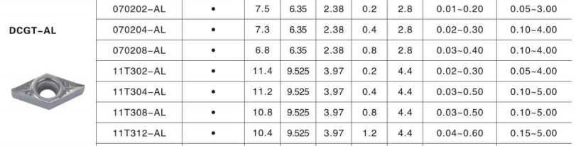
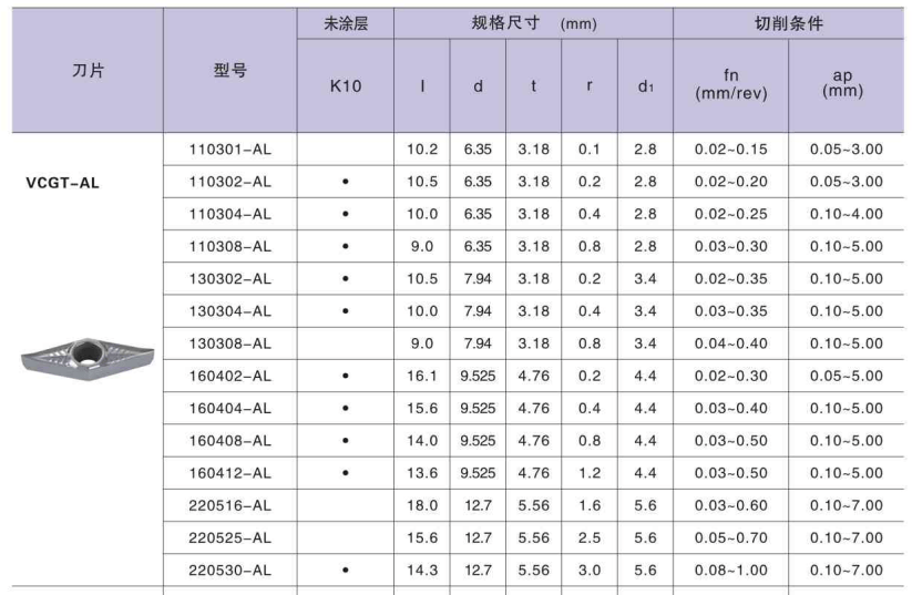
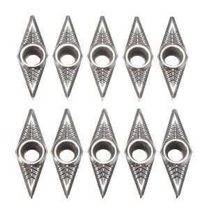
Are you looking for inserts made of carbide for aluminum? Compatible with each and every type of carbide insert. Carbide inserts that are both durable and of a high grade are used for cutting metal. Carbide is used in the construction of the main body, which has the capability of cutting through a variety of materials, including aluminum, plastic steel, and other metals. At the same time, carbide inserts, which are known for their extreme toughness and long-lasting nature. Inserts made of carbide for aluminum and copper, in the meantime. Carbide inserts are utilized for applications involving aluminum, and are paired with high-speed steel blades. Cnmg insert for aluminum, in addition to other great offers on machinery and supplies, can be found at Huana. Keep an eye out for sales and specials if you want to receive a significant discount on the apkt 1604 inserts for aluminum you purchase. At Huana, you’ll find an excellent selection of carbide insert for aluminum at competitive pricing. We won’t judge you for shopping for Carbide inserts for aluminum so frequently because the costs are so low. We are here to assist you in taking advantage of as many of the available discounts as possible, given all the different specials. Visit Huana, and have a fantastic time while you’re there shopping!
When working with turning applications, it is vital to use the correct form of an insert, and this shape is decided by the suitable point angle in order to maximize both strength and economy. The needs of the application and the amount of room available in the application for the cutting tool will determine the appropriate size of the carbide inserts to use when working with aluminum. Large insert sizes necessitate more stability when working with robust machinery; the usual size of apkt 1604 inserts for aluminum often climbs up to 25 millimeters. After the project is finished, the height of rotation may frequently cause a reduction in the scale of the insert.
How Do You Determine the Appropriate Size for Carbide Inserts Aluminum?
- Eliminate the most important amount of the cut depth.
- Find the needed cutting length, also known as LE, taking into account the tool holder entrance angle, the cutting depth, and the machine specification.
- Check that the right slice length for the insert is known to you.
Carbide insert for aluminum are utilized most commonly with aluminum; however, they are adaptable enough to meet the requirements of materials such as wood and acrylics. Machining aluminum successfully requires making adjustments to the process in order to take into account the material’s unique properties.
Implementing these tips will help you reduce the difficulties and generate high-quality components.
- Determine the Appropriate Feeds and Speeds
The optimal combination of feeds and speeds for cutting aluminum, as is the case with the vast majority of metals, falls within a more constrained range than those for cutting wood or acrylics. The process of cutting aluminum necessitates a faster spindle speed, which may test the capabilities of your carbide insert for aluminum to their absolute maximum. A rubbing that shortens the life of tools can be caused by feed rates that are too sluggish.
Feed rates that are excessively quick can overwhelm the machine, which can lead to the equipment breaking down. The time-honored practice of "playing it by ear” leaves much too much leeway for mistakes to be corrected. You will be able to compute rates with more accuracy if you use a calculator that takes into account both feeds and speeds.
- Carbide-Coated Bits Of Ever Smaller Diameters Should Be Used
Because cutting aluminum requires higher RPMs, high-speed steel and cobalt are not likely to be enough for the job. Because of its higher degree of brittleness, carbide is an excellent choice for use in?carbide inserts for aluminum manufacturing. In order to achieve faster machining rates, smaller diameter carbidevcgt 160402for aluminum are required. Another advantage of this situation is that the stiffness of the carbide will defend against any tool deflection that may occur.
- Maintain a Consistent Temperature
Aluminum is more susceptible to changes in temperature, which might result in waste as a result of finished components that are not within tolerance. Utilize computer hardware and software that are capable of maintaining temperatures at a level that is acceptable.
- Clear Chips Properly
Because aluminum chips have a particular "stickiness” element, they have a tendency to adhere to the tool in such a way that they virtually weld themselves to it. This results in subpar work and excessive wear and tear on the machinery. You shouldn’t put all of your faith on the dust collector systems. Always again check the vcgt 110304?insert to make sure that all of the chips have been removed. Reduce the likelihood of chips sticking together by circulating a coolant mist or another type of lubricant through the machine.
- Proceed With Caution
It is tempting to make larger cuts with vcgt 160402 inserts for aluminum in order to save time, but this tactic might backfire since it makes it more difficult to clear chips from the table. Continue using many shallow passes, since this will provide you with greater control as well as better access for chip removal.
- Reduce the Flutes’ Number
The presence of an excessive number of flutes in vcgt 160404?insert might make the chip issue worse by leading to an excessively close packing of the chips. When working with metal, reduce the number of flutes to no more than three for carbide inserts for aluminum. When there is more room in between the cutting blades, it is much simpler for bigger chips to slip through.
Creating properly completed components is now achievable thanks to our revolutionary stacked aluminum machining ccgt insert, which eliminates the need for the time-consuming and laborious traditional stacking, drilling, and riveting processes.
Our extensive collection of light, medium, and heavy-duty Groove Aluminum inserts provides options that are suitable for a wide variety of applications and industries.
How to buy Groove that suit for aluminum?
The process of choosing the right Aluminum groove that best meets your requirements may be broken down into the following easy phases.
First, Determine The Diameter Of The Wheel
If you are replacing an existing Aluminum wheel, this should be a reasonably smooth process for you; but, if you are ordering for a new application, you should consider how you want to mount it to your apparatus as well as the weight that it needs to hold before placing your purchase.
Second Step, Select the Appropriate Aluminum Groove Material
When it comes to your castors and wheels, this is potentially a very crucial factor to take into Carbide Milling Inserts account.
- Will the castor be utilized in an outdoor setting?
- Will the wheels come into touch with any substances that might be dangerous or corrosive?
- Will the wheels be capable of supporting excessive weights, such as up to one ton?

Third Step, Check the Load Capacity
You need to be aware of the load capacity of your castor wheels in order to prevent them from collapsing under excessive weights. However, you do not want to over-specify the castor wheels (for example, ordering those with a capacity of 500 kilograms when you only need those with a capacity of 200 kilograms), as the cost of the castor wheels will typically increase in proportion to the weight of the load.
How do you determine the load capacity?
- Take into consideration how heavy the tool is.
- The utmost weight that can be supported by it
- First, add all of them together to determine the overall weight or burden, and then divide the amount by three.
- The final number will represent the maximum weight that each castor should be able to support.
How to Select?the Best Carbide Insert for Aluminum?
A number of variables contribute to increased productivity while milling aluminum. Choosing the appropriate insert is critical to effectively and economically cutting metal. Use the information below or contact Huana for carbide insert for aluminum selecting guidance from qualified technical consultants.
- Insert Geometries
Carbide insert for aluminum are typically advised when bigger diameters, higher feed rates, and deeper cuts are used, or simply when changing inserts is preferable to regrinding a high-speed steel or brazed carbide tool for a variety of reasons. The usual insert substrate is tungsten carbide, which is more brittle than high-speed steel. Many ccgt 060204 inserts feature several cutting edges (for indexing), post-processing treatment (such as grinding, polishing, or coating), and may be available in varying radii depending on the application. Indexable tool holder shanks as tiny as 1/4″ may be found for lathes, while indexable milling diameters as small as 3/8″ can be obtained for milling machines.
Insert shape, rake angles, and relief angle are three primary geometries that have a significant impact on ccgt 09t304 insert performance. Because aluminum is a slippery and free-machining material, sharper angles are usually advised to aid shear through the material rather than pushing it with a honed or dull cutting edge.
- Shape of?Insert
When making smaller quantities or prototypes, the primary deciding element of an insert may simply be the tool holder available for that application, and many holders will have specialized geometries for cutting aluminum. Round, triangular, square, parallelogram, and diamond-shaped inserts can all be employed advantageously. When selecting an insert form, it is usually advised that the most acute angle be chosen after taking into account the specified application, clearance, depth of cut, feed rate, and amount of interruption that the application will allow. The geometry of the insert can increase application efficiency, effectiveness, and tool life. For example, a sharp 35° diamond shape might assist a high-speed finishing application in single-point turning of aluminum, but you may wish to avoid a sharp 35° diamond shape on sand-casted aluminum with a rough surface and use a round-shaped insert.
- Relief Angles
The relief angle is the angle formed between the workpiece and the cutting tool, often on the insert’s side. Relief angles are classified into two types: positive and negative. Any angle larger than zero is called positive relief, whereas any angle equal to zero is considered negative relief. The location of an insert on the holder can change the total relief; for example, an insert with a 20° relief can be angled to raise its overall relief to 25°. The relief angle, in combination with the rake angle, influences the cutting process and its outcome.
- Rake Angles
The rake angle is the angle between the cnmg insert for aluminum tip and the workpiece. Rake angles are classified as negative, neutral, or positive. A positive rake angle is excellent, and most manufacturers will employ their greatest positive angles for cutting geometry. A good rake angle aids in chip disposal, reduces insert cutting resistance, lowers cutting temperature, reduces built-up edge (BUE), improves machinability, and lowers cutting power needed. Caution is required since a positive rake angle is prone to fracture and should not be used on ferrous or difficult-to-cut materials.
- Chipbreakers
Aluminum chips are sticky and can become overwhelming quickly. A chipbreaker with a high positive and sharp edge is suggested. Rake angles and sharp cutting edges are typically emphasized with aluminum / non-ferrous specialized chipbreakers and are too sharp for many other materials.
Aluminum Machining Special Chipbreaker:
Chip pocket with a high rake angle and a tabby pattern: low cutting load aluminum chipbreaker
- Design with a unique rake angle:excellent chip breaking and smooth chip flow
- Top face that is unique and 3-dimensional:longer tool life and great surface roughness
- Sharp cutting edge and tabby pattern:dispersed cutting load, extended tool life
- Buffed on top face:better machining and chip flow, less built-up edge
Conclusion
However, because there are so many variables to consider, if you want to improve the efficiency and predictability of your aluminum milling operations, the best course of action is to collaborate closely with the cutting tool manufacturer. This is the most effective technique to reach your goal. By contacting HUANA, you may obtain the best carbide insert for aluminum in a range of shapes and sizes.
The Cemented Carbide Blog: Turning Inserts
Posted by: philipryan at
07:52 AM
| No Comments
| Add Comment
Post contains 2110 words, total size 22 kb.
April 08, 2024
Tungaloy has introduced BX330 CBN grade inserts for its TungThread thread turning tool series. The series offers a range of thread turning inserts and toolholders, covering applications TNGG Insert from general threading on CNC lathes and fine threading of precision parts machined Carbide Inserts on Swiss-type lathes to high-precision premium threads of OCTG pipe connections.
Two new BX330 grade inserts have been added to the series’ 60º partial profile threading insert line: 1QP-16ER60-014-SP and 1QP-16ER60-020-SP, both of which feature a brazed CBN tip.
Turning threads on hardened parts can be a challenge when using coated cemented carbide inserts, according to Tungaloy. The cutting edge can wear out quickly, leading to slower feed rates and less productivity. Of all Tungaloy CBN grades, the company says its BX330 provides the cutting edge with the most balanced combination of wear and fracture resistance. The grade is suitable for withstanding continuous and heavy cutting loads common in the thread turning method for hardened parts.
Featuring the standard 16ER laydown insert shape, the CBN threading inserts can be used with existing TungThread toolholders. With this addition, TungThread supports hard part threading applications with a wide range of standard toolholder sizes available for thread turning.
The Cemented Carbide Blog: http://philipryan.mee.nu/
Posted by: philipryan at
06:40 AM
| No Comments
| Add Comment
Post contains 211 words, total size 2 kb.
April 02, 2024
Plastics and its usages are the trending topics across the globe. The government has taken various important steps to reduce plastic waste that can further harm the environment. Recycled HIPS pellets are such assets, processed for preserving the surround from plastic TCMT Insert wastes. Plastic is not biodegradable, and hence, as per predictions, the ocean may include tonnes of plastic waste in the coming years.
This will be very harmful to marine lives and for human beings as well. Therefore, the industries are moving to use recycled HIPS pellets for their productions, as this is a good way to utilize the waste materials. GRM Polymer is a renowned company to support and make the recycling process possible. It provides high-quality plastic compounds to match the precise requirements of Polystyrene and Recycled HIPS pellets.
1. Sorting
Companies field perform sorting either manually or with machines. If sorted through machines, they should be technically able to recognize the various sorts of plastic. The advanced sorting machines can recognize and separate large amounts of plastics. Color detection and ejectors are instrumental in handling this task.
2. Resizing
After sorting, resizing is the next step, which involves the processing of plastic waste and converting them into smaller sizes. The shredders and granulators perform this size reduction task with ease. The industries also comprise advanced machines having rotational cutting blades to perform the task. These blades are responsible for chopping down the plastics to carry forward for the next step. Many industries seek regrinds and shreds before Recycled HIPS pellets. Therefore, some recyclers complete their process in this phase to serve the relevant industries. It maintains the quality and standards of the product.
3. Wet and dry separation
After the above two steps, the third step is granule separation, where the experts wash processed plastic pieces to remove the dirt and dust. The process may vary as per the plastic types. Washers and float tanks are helpful in washing and separating the pieces accordingly. The hot water sprays are highly useful for the sake of improving the separation and cleaning process.
The separation offers the differentiation and classification of the plastic pieces depending on the shape and size of the plastic. Many other factors also play an effective role in this respect, like melting point, absorption of light, etc.
4. Compounding
Compounding is the final step of the entire recycling process. Here the professionals convert plastic regrinds into pellets like Recycled HIPS pellets, as it becomes easier to process the plastic in pellet form. These elements undergo further use for making high-quality reusable materials.
Recycled HIPS pellets and other pelletize originate from plastics through sophisticated machines, Coated Inserts better known as extruders, either with single or double screws. The raw materials produced from sustainable sources are cost-effective as well. The advancement in technologies has increased industry standards efficiently. It has given way to quality pellets for better plastic utilization, and GRM Polymer is the best in this particular cause. The company safeguards the environment with its recycled HIPS pellets. It helps organizations representing varied sectors in providing quality storage and package solutions through these HIPS pellets.
The Cemented Carbide Blog: tungsten carbide Inserts
Posted by: philipryan at
04:03 AM
| No Comments
| Add Comment
Post contains 536 words, total size 4 kb.
34 queries taking 0.044 seconds, 102 records returned.
Powered by Minx 1.1.6c-pink.

